Introduction to Inductively Coupled Plasma and Microwave Plasma Modeling
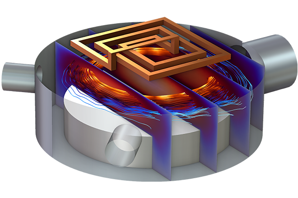
In Part 4 of this course on modeling nonequilibrium plasma using COMSOL Multiphysics® and the Plasma Module, we take a closer look at the Inductively Coupled Plasma interface. We go over what type of modeling the interface is used for as well as the physics that the interface combines. You will also see a breakdown of what each constituent physics interface under the Inductively Coupled Plasma multiphysics interface solves for and how the multiphysics are coupled. This includes the:
- Plasma interface — solves for plasma in the time domain
- Magnetic Fields interface — solves for magnetic vector potential in the frequency domain
- Plasma Conductivity Coupling feature — couples the plasma conductivity with the Magnetic Fields interface
- Electron Heat Source coupling feature — couples the power deposition for electrons with the Plasma interface
We also discuss the additional multiphysics couplings that are available, such as the Collisionless Heating Coupling feature.
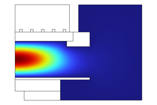
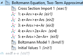
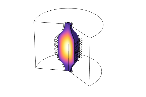
Following this review, we encourage you to follow along as we demonstrate how to build a model of a GEC ICP (inductively coupled plasma) reactor step by step. The collision cross-section data that needs to be imported during the demo using the Plasma interface > Global > Cross Section Import operation can be found in the linked Application Gallery entry. We also show how to create a user-defined mesh to discretize the model geometry, and explain the logic in doing so for the plasma domain rather than other domains, such as the coil.
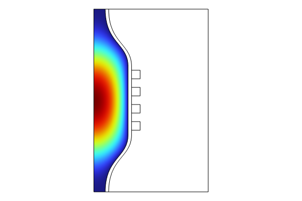
We then provide a similar introduction to the Microwave Plasma interface. We will cover:
- What it solves for and the equations involved
- How it combines the Plasma interface and Electromagnetic Waves, Frequency Domain interface
- How the physics are coupled
When discussing the multiphysics coupling for the plasma conductivity, there is a special emphasis on the Compute Tensor Plasma Conductivity section within the settings.
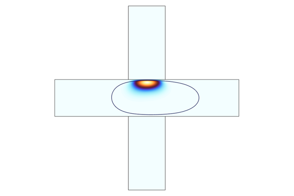
There is then another guided model demonstration, this time of a model that simulates in-plane microwave plasma, where a wave is launched down a waveguide and intersects a flowing gas. The results between launching a transverse electric (TE) and transverse magnetic (TM) wave are compared. Following the demo, we briefly discuss the resonance zone and the Port boundary condition before sharing other resources for learning about microwave plasmas, including our "Microwave Plasmas" blog post.
Envoyer des commentaires sur cette page ou contacter le support ici.

