La Bibliothèque d'Applications présente des modèles construits avec COMSOL Multiphysics pour la simulation d'une grande variété d'applications, dans les domaines de l'électromagnétisme, de la mécanique des solides, de la mécanique des fluides et de la chimie. Vous pouvez télécharger ces modèles résolus avec leur documentation détaillée, comprenant les instructions de construction pas-à-pas, et vous en servir comme point de départ de votre travail de simulation. Utilisez l'outil de recherche rapide pour trouver les modèles et applications correspondant à votre domaine d'intérêt. Notez que de nombreux exemples présentés ici sont également accessibles via la Bibliothèques d'Applications intégrée au logiciel COMSOL Multiphysics® et disponible à partir du menu Fichier.

This model uses the Semiconductor and RF modules to describe a photoconductive antenna (PCA). A laser pulse is applied on the surface of undoped LT-GaAs to generate electron-hole-pairs, which move under the influence of an external E-field creating a transient electric current pulse. ... En savoir plus
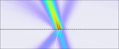
This shows how a Gaussian beam incident on a periodic structure can be efficiently simulated. This could be applied to structured surfaces like metasurfaces or diffraction gratings. Because of superposition, only a single unit cell needs to be simulated. This can provide extremely ... En savoir plus

In this tutorial, an uncertainty quantification analysis is performed on the Microstrip Patch Antenna model from the RF Module Application Library to explore how variations in input parameters, such as material properties or geometric variations, impact the antenna’s performance in terms ... En savoir plus

Substrate Integrated Waveguides (SIW) can be used in antenna applications. Leaky waves from a slot array on the top surface of the SIW in this model generate a beam in a certain direction that can be steered by choosing a different operating frequency. En savoir plus
One way to generate circular polarization from a microstrip patch antenna is to truncate the patch radiator. This model is tuned around the GPS frequency range. The axial ratios are calculated to show the degree of circular polarization. En savoir plus
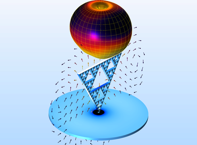
A fractal is a mathematical form showing self-repeating patterns. By virtue of its geometrical properties, a fractal structure can generate multiple resonances in RF applications. This antenna model uses a 3rd order Sierpinski triangle and the calculated S-parameters shows good input ... En savoir plus

Transmission lines are used when the frequency of the electromagnetic signals is so high that the wave nature of the signals must be taken into account. A consequence of the wave nature is that the signals are reflected if there are abrupt changes of the characteristic impedance along ... En savoir plus

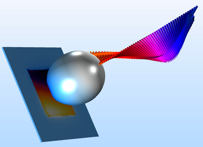
A plane electromagnetic wave is incident on a metallic sphere partially embedded on a substrate. In this electromagnetic scattering problem, the far-field variables are computed for a few elevation angles of incidence. En savoir plus

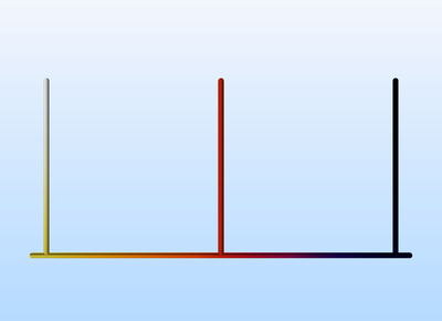
Some conventional three-port power dividers are resistive power dividers and T-junction power dividers. Such dividers are either lossy or not matched to the system reference impedance at all ports. In addition, isolation between two coupled ports is not guaranteed. The Wilkinson power ... En savoir plus
One way to design a filter is to use the element values of well-known filter prototypes, such as maximally flat or equal-ripple low-pass filters. It is easier to fabricate a distributed element filter on a microwave substrate than a lumped element filter, since it is cumbersome to find ... En savoir plus